Brushed DC motors are cheap and robust, but inherently hard to control accurately compared to modern BLDCs, especially at low speeds. This is fine for applications like household appliances or electric power tools, where positioning and precise speed control aren’t needed. For a skid steer robot, however, it is a prerequisite even for just driving a straight line. So, let’s see what we can do.
Outline of what we will do:
- Linearize the output voltage of our H-Bridge
- Create an open-loop speed controller
- Add a closed-loop speed controller on top
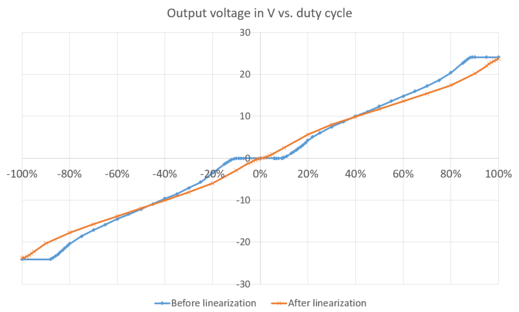
Linearize H-Bridge Output Voltage
A prerequisite to predictable motor behavior is a predictable voltage source.
Measuring the output voltage vs. duty cycle reveals: Our H-Bridge module does not output a voltage that’s proportional to the duty cycle of the PWM signal we use to control it.
This is due to a protection feature that introduces some dead time when switching, to avoid shoot-through conditions. It’s great to have it, but we want this detail to be transparent to our control loop.
To achieve that, we simply map the full range of PWM duty cycles (0…100%) to the ranges of approximately linear behavior (9.2…89%), both for the negative and positive output ranges.
In Part 3 we will use our linearized H-Bridge output to control our motors.
1 Antwort zu “Linearize H-Bridge Output Voltage (Big rover robot platform – Part 2)”