We want to control rotational speed [n] in rpm, which is proportional to back-emf [e] in V. They are related via the motor constant [Kv] in rpm/V.
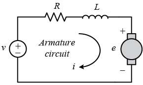
Unfortunately, we actually can’t directly control e, since the motor windings, brushes, leads, and also our H-Bridge MosFETs add inductance L and resistance R to the circuit.
We’ll ignore the inductance for now, but the resistance has a very easily observable and unsurprising effect: A constant voltage input v to the motor won’t result in a constant rotational speed n under varying load, since depending on the current [i] in A, some of our voltage gets lost across R.
So first of all, we want to compensate for R so we’re able to virtually control e (and therefore n) as we wish.
To do so, we simply calculate the voltage drop across R and add it to v to compensate for it.
Since R is approx. constant, we can just measure it once by blocking the motor, applying some voltage, and measuring the current. Blocking the motor ensures no voltage drops across inductance L.
R then is U/I, which we get from applying an arbitrary voltage across the motor leads and measuring the current.
Motor current i during actual operation on the other hand changes depending on the load on the motor, so we need to keep measuring it while driving to constantly update our compensation.
Now we have all the information we need to try and control the rotational speed [n] in rpm of the motor. We know n = e*Kv, and we can approximate v = e + R*i. Solving for the terminal voltage v, we get v = n/Kv + R*i.
Fortunately willfully applying that voltage v is what we already achieved in Part 2.
1 Antwort zu “Create an open-loop speed controller (Big rover robot platform – Part 3)”